Virtual Null Modem & Virtual Data Monitor (V2)
Back to Hard&Software | Download Demo Version (about 3.8 MB)
Use this link for an update for Windows 7 and later. Or, better, get a copy of my book, which provides an improved version.
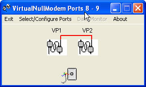
Figure 1
Virtual Null Modem is an application that creates two "Virtual Serial Ports" and a provision for connecting to an external physical serial port (or a virtual serial port, such as that used with a USB serial adapter or GPS receiver). The application normally runs as an item in the Windows Task Bar. When first opened, you will see a window similar to the one above (Figure 1). The Red line connecting the two port icons indicates that one or both of the virtual serial ports are closed.
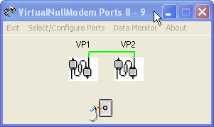
Use the Select/Configure Ports menu to assign port numbers to VP1 and VP2. A virtual serial port will be created that may be opened and used by other applications, using standard Windows serial communications APIs. For example, Windows HyperTerminal works well with the virtual serial ports created here. When both virtual serial ports have been opened by some other application or applications, the line connecting the port icons turns Green (Figure 2). This mode is called VirtualNullModem. The Port Configuration screen is shown in Figure 3.
 .
.
Figure 2
In VirtualNullModem mode data then may transmitted from each to the other, without requiring physical serial ports or a null modem cable or connection. This is a great tool for debugging and testing serial applications.
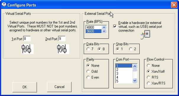
Figure 3
An alternate mode is provided to allow an external physical serial port (or an external virtual serial port, such as the one used by a USB serial adapter or USB GPS receiver) to be connected to either or both of the Virtual Serial ports that have been selected. Select the port number (Com Port) -- port numbers from 1-255 are supported, speed (Rate), parity, stop bits, and flow control to be used by the external port. When you check Ö the Enable checkbox, the selected port will be opened.
When the external serial port has been enabled, the application no longer acts as a null modem, rather it acts like a "Y" cable. The VirtualY mode connects the external port to either or both of the virtual serial ports. Thus, any data received via the external serial port is directed to one or both virtual serial ports. Any data sent by the application(s) that are using the virtual serial ports are directed to the physical serial port and are sent to the hardware device that is connected to that port! Figure 4 shows the possible logical connections, ranging from no connection (neither Virtual Serial Port has been opened by an external application) to one Virtual Serial Port open, and then both Virtual Serial Ports opened.
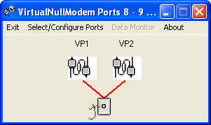
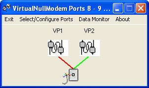
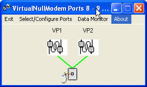
Figure 4
But there is more! The VirtualDataMonitor™
What is more natural, and useful, than to be able to view data sent and received by your serial applications? Well, when everything is working well, then... You don't need this function. However, during design, debug and test (or test and debug), viewing serial data in various display formats can not only be useful, but vital! Enter the VirtualDataMonitor function. When an application program has opened both Virtual Serial ports in VirtualNullModem mode, or when either or both Virtual Serial ports have been opened by applications when operating in VirtualY mode, then the Data Monitor menu item is enabled.
Serial data sent and received may be viewed in one or two displays. Here are the various display means that are provided (the font colors selected were in honor of Flag Day, 2006).
VirtualNullModem with separate windows for each port
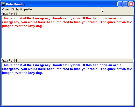
Figure 5
Figure 5 shows this connection, with a simple ASCII display (non-ASCII characters are not displayed).
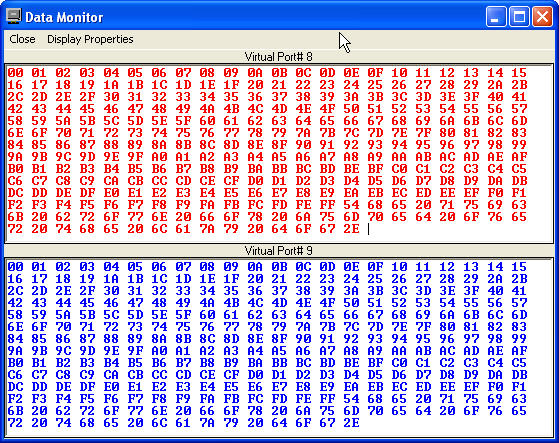
Figure 6
Figure 6 shows the same VirtualNullModem with data displayed in hexadecimal format. Often these two display modes will be sufficient. However, there are times when these simple displays hide critical timing information. That is, data sent and received by the associated programs may interact (commands and responses, for example), and the relationship between each may not be obvious. Thus, another operational mode is available, where data sent and receive by each port is displayed in a single window. This display mode is termed "Interleaved." Two examples are shown (Figures 7 and 8), ASCII and hexadecimal, respectively. This display mode shows the actual order that data is received by the applications attached to each Virtual Serial Port. You may select the colors to be associated with each port using the Display Properties menu (described later).
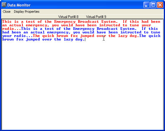
Figure 7
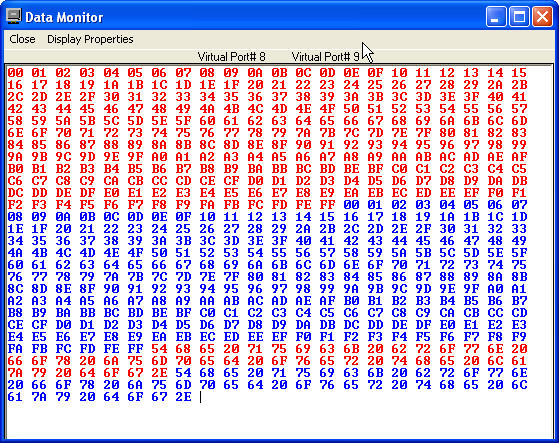
Figure 8
Similar displays are provided when using VirtalY mode. Figures 9 and 10 illustrate the displays. No data have been sent by the application connected to the Virtual Serial Port (Com8) in these figures. Had data been sent, it would have been displayed in red in the respective windows. Each windows is labeled to show which port is associated with which window.
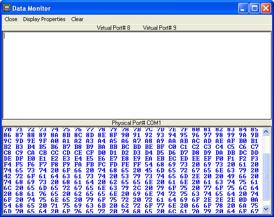
Figure 9
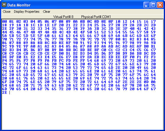
Figure 10
When the VirtualY connection is used, and the "Interleaved" mode has not been selected, both Virtual Serial Ports (if both are active) are displayed in the upper window. In this case, that data in that window is automatically "interleaved." Colors are used to distinguish the data from each Virtual Serial Port. See Figure 11.
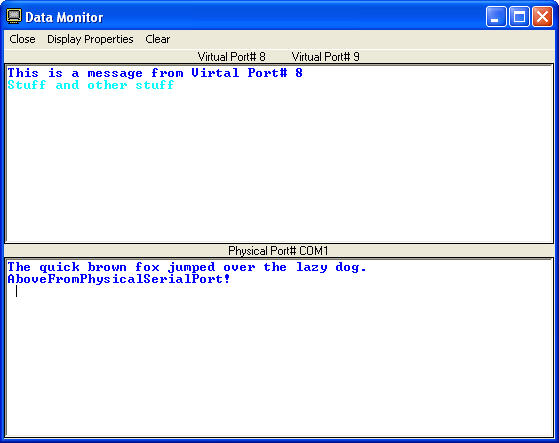
Figure 11
Upon occasion it is important to display ASCII control characters (which normally are not shown) in addition the ASCII string data. In addition, some non-ASCII data, with character values higher than x00F0 (128 decimal) may be part of the serial data stream. Display of these non-ASCII characters depends on the font used, and the Windows Code Page that is in use. I have added a mode that allows these various characters to be displayed and interpreted logically, without relying on font or code page. For this, I first want to describe the Display Properties dialog.
Display Properties
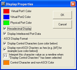
Figure 12
The Display Properties dialog allows you to configure the colors associated with each port, ASCII/hexadecimal display, and the use of a single window to "interleave" data from each port in the order that is was received. In addition, several extra ASCII display parameters may be configured. We can enable the display and decoding of ASCII Control Characters, and the display (without decoding) of the hexadecimal value of any non-ASCII characters that may be in the data stream. The color used to display these special characters also is selected here. Figure 13, below, illustrates the results of enabling this display mode with a mix of data that includes both ASCII control characters, ASCII text, and non-ASCII binary data -- interleaved with data from the applications connected to each Virtual Serial Port. Note that ASCII control characters are displayed with a pneumonic that represents each conventional function, and that the non-ASCII data hexadecimal value is displayed inside a bracket -- both ASCII control characters and non-ASCII data should be assigned a unique color to enable reliable visual recognition.
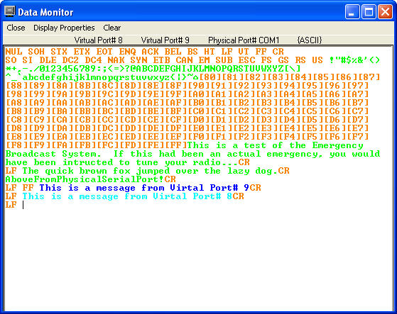
Figure 13
Demo Version
The Setup program contains a "Demo" version of the program. It displays a MsgBox with a copyright message on startup, and the VirtualDataMonitor mode is limited to 60 seconds of continuous display. If you find the program to be valuable, you may want to purchase a version without the MsgBox. This is bargain priced! You can purchase it for $20. Contact me directly for this, or use the button below. For this low cost, I cannot provide much in the way of support. However, I will try to answer specific questions. Naturally, I am available for consultation at my regular hourly rate.
Source Code
Source code also is available at additional cost. Contact me here for this.
Update History
Updated 5 May 2007. Fix bug in hex display of data from the virtual serial ports.